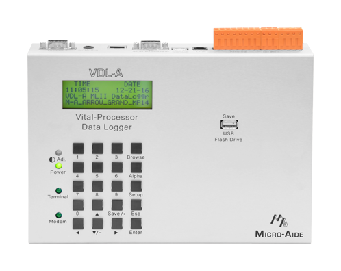
On the Outside
80-Character LCD
The LCD and Keypad allow an onsite user to fully access the device without using a PC. Access is protected by an 8-digit Passcode.
20-Position Keypad
The LCD and Keypad allow an onsite user to fully access the device without using a PC. Access is protected by an 8-digit Passcode.
3 Front Panel LEDs
LEDs are used to indicate power, Terminal Port and Modem activity.
USB Host Port
A user-selected range of Event Records can be quickly saved to a USB Flash Drive. Both text and GEA-version records are saved.
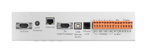
Serial Terminal Port
Baud rates from 300 to 115,200 are supported. The default Baud rate is 38,400. The Terminal Port can be used with a USB-to-serial adapter.
GPS Receiver (opt.)
Without user intervention, the internal real-time clock (RTC) can be kept 100% accurate by using the GPS Receiver option. The option comes with an external, ruggedized antenna.
Ethernet Port (opt.)
The Ethernet Port option allows remote users to access the device via a LAN connection. Additionally, if a time server is accessible it can be used to maintain 100% RTC accuracy.
Port to Vital Processor
This port connects directly to port 3 or 4 of the Microlok II. Baud rates from 300 to 115,200 are supported. The default Baud rate is 9600.
USB Device Port
The USB Device Port provides a very high speed alternative to the serial Terminal Port. It is crucial for PC's lacking a serial comm port and when a USB-to-serial adapter is not available.
Internal Modem (opt.)
The internal Modem option can be used with a typical land line to provide remote access. Access is restricted by means of a user-defined password. It supports speeds up to 33,600 Baud.
4 Analog Inputs
Positive and negative DC and AC voltages are continuously monitored by the Analog Inputs. Separate user-defined High and Low Limit Values are used to identify abnormal conditions.
Relay Output
User-programmed Virtual Inputs control the operation of the Relay Output. It can be used to provide an external indicaton of a fault or failure condition.
BN Power
Typical battery power can be used to power the device. Its operating range is 9 to 36Vdc. The internal power supply is fully isolated.
Detachable Connectors
All input, power and relay connectors are detachable for ease of installation. Tension clamp connectors are used throughout.
VDL-A MLII Documentation

On the Inside
Connects to Port 3 or 4 of Microlok II
A MICRO‑AIDE supplied 3‑wire cable is used to make the physical connection between both devices.
Supports US&S/Ansaldo Peer Protocol
The Peer Protocol limits the behavior of the VDL‑A to that of a recieve only device. The protocol implements an ack/nak exchange to prevent erroneous data from creating false Event Records.
Reports Bit Transitions as 256 Digital Inputs
The VDL‑A supports 2 separate station assigments, each of which can represent 128 bits.
Operates Strictly as a Non-Vital Device
The Peer Protocol limits the VDL‑A interaction with the Microlok II to that of a non-vital device.
Up to 128 days of Event Storage
Irrespective of how many days are saved in memory, after the memory is filled new data automatically overwrites the oldest data. Similarly, the 129th day overwrites the first day.
284,785 Event Record Storage Capacity (exp.)
Memory can be optionally expanded to 1,182,769 Event Records.
Events Time Stamped to .1 sec.
Event Records can be continuously time stamped to a resolution of .1 sec. for all 256 bits.
Non-Volatile Memory With No Internal Batteries
Event Records and the Setup Database are retained indefinitely, even when power is not applied. There are no batteries or other consumables to replace.
Clock Accuracy ±8 sec. per Month (std.)
Even in the absence of clock synchronization the RTC is highly accurate. The clock will continue to run with a loss of power of up to 30 days duration.
100% Accurate Clock (opt.)
The GPS Receiver and Ethernet Port options can be used to maintain 100% accuracy of the RTC. Using the Ethernet Port option for this purpose requires an accessible time server.
Sets Accurate Time in Microlok II (opt).
The GPS and Ethernet options can be used to maintain 100% accuracy of the VDL‑A's RTC. If enabled, the Peer Protocol will allow the VDL‑A to set the RTC of the Microlok II. Accordingly, data from both devices will be time synchronized and accurate.
8 Programmable Virtual Inputs
Logical conditions among any 4 Digital, Analog or other Virtual Inputs are automatically detected using the Virtual Input feature. These conditions, that may be of special interest to the user, are logged to memory as Event Records.
16 Programmable Timer Inputs
The duration between any 2 events can be measured and reported as an Event Record. User-defined High and Low Limit Values can be used to detect abnormally long or short durations.
Internal Temperature Sensor
The internal temperature of the device is continuously monitored. Excessively hot or cold conditions are logged to memory as Event Records.