On the Outside
Modularly Expandable
Each system comprises a single Primary Unit that supports 1 to 16 Secondary Units. Each Secondary Unit is equipped with 256 Digital and 4 Analog Inputs.
Ethernet Based
The Primary Unit communicates with each Secondary Unit using industry standard Ethernet protocols. A 24-Port Ethernet switch is used to implement the intra-system LAN.
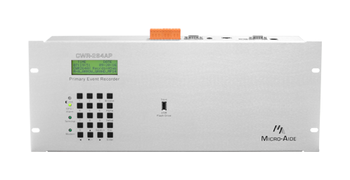
80-Character LCD
The LCD and Keypad allow an onsite user to fully access the system without using a PC. Access is protected by an 8-digit Passcode.
20-Position Keypad
The LCD and Keypad allow an onsite user to fully access the system without using a PC. Access is protected by an 8-digit Passcode.
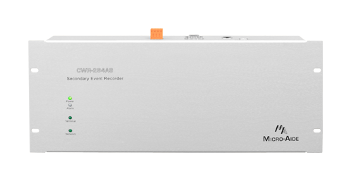
Front Panel LEDs
LEDs are used to indicate power, alarm, Terminal Port and Modem activity.
USB Host Port
A user-selected range of Event Records can be quickly saved to a USB Flash Drive. Both text and GEA-version records are saved.
Std. 19" Rack Mount
23" rack mounting adapters are available upon request. Approximately 10.5" of vertical rack space is required per unit.
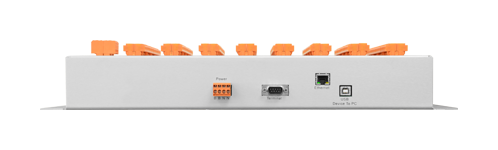
BN Power
Typical battery power can be used to power the system. Its operating range is 9 to 36Vdc. The internal power supplies are fully isolated.
2 Relay Outputs
User-programmed Virtual Inputs control the operation of the Relay Outputs. They can be used to provide an external indicaton of a fault or failure condition.
2 Serial Terminal Ports
Baud rates from 300 to 115,200 are supported. The default Baud rate is 38,400. The Terminal Ports can be used with a USB-to-serial adapter.
GPS Receiver (opt.)
Without user intervention, the internal real-time clock (RTC) can be kept 100% accurate by using the GPS Receiver option. The option comes with an external, ruggedized antenna.
Ethernet Port
The Ethernet Port allows remote users to access the system via a LAN/WAN connection. Additionally, if a time server is accessible it can be used to maintain 100% RTC accuracy.
USB Device Port
The USB Device Port provides a very high speed alternative to the serial Terminal Ports. It is crucial for PC's lacking a serial comm port and when a USB-to-serial adapter is not available.
Internal Modem
The internal Modem option can be used with a typical land line to provide remote access. Access is restricted by means of a user-defined password. It supports speeds up to 33,600 Baud.
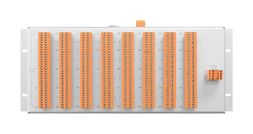
256-4096 Digital Inputs
All Digital Inputs are fully isolated by optical means. On/off conditions are 9 to 36Vdc and 0 to 1Vdc, respectively.
4-64 Analog Inputs
Positive and negative DC and AC voltages are continuously monitored by the Analog Inputs. Separate user-defined High and Low Limit Values are used to identify abnormal conditions.
Detachable Connectors
All input, power and relay connectors are detachable for ease of installation. A combination of tension clamp and screw-down connectors are used throughout.

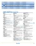
CWR‑264AX Documentation

On the Inside
Up to 128 days of Event Storage
Irrespective of how many days are saved in memory, after the memory is filled new data automatically overwrites the oldest data. Similarly, the 129th day overwrites the first day.
5,080,576 Event Record Storage Capacity
Each system is equipped with the maximum amount of storage capacity.
Events Time Stamped to .01 sec.
Time stamping at 1/100th of a second can be useful when monitoring high speed or short duration electronically generated signals.
Non-Volatile Memory With No Internal Batteries
Event Records and the Setup Database are retained indefinitely, even when power is not applied. There are no batteries or other consumables to replace.
Clock Accuracy ±8 sec. per Month (std.)
Even in the absence of clock synchronization the RTC is highly accurate. The clock will continue to run with a loss of power of up to 30 days duration.
100% Accurate Clock (via SNTP)
The GPS Receiver option and Ethernet Port can be used to maintain 100% accuracy of the RTC. Using the Ethernet Port for this purpose requires an accessible time server.
Tamperproof Event Records
At the user's discretion, an Event Record report can be digitally signed. The signature can be used to detect alterations of the report.
32 Programmable Virtual Inputs
Logical conditions among any 4 Digital, Analog or other Virtual Inputs are automatically detected using the Virtual Input feature. These conditions, that may be of special interest to the user, are logged to memory as Event Records.
99 Programmable Timer Inputs
The duration between any 2 events can be measured and reported as an Event Record. User-defined High and Low Limit Values can be used to detect abnormally long or short durations.
16 Programmable Train Speed Monitors
The monitors calculate the average front-of-train speed. A user-defined Limit Value is used to report excessive speed.
Flash Rate Reporting and Measurement
This feature can be used to precisely measure the flash rate. Additionally, the flash rate is reported in each Event Record when flashing is present.
Internal Temperature Sensor
The internal temperature of each unit is continuosly monitored. Excessively hot or cold conditions are logged to memory as Event Records.
Modbus Provides Real-Time Status
The Modbus over TCP/IP interface provides continuously updated status of all Digital and Analog Inputs.