On the Outside
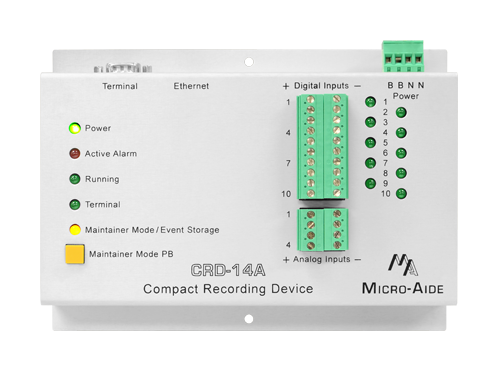
5 Activity Indicator LEDs
Active Alarm conditions and several other important activities are indicated by the front panel LEDs.
Maintainer Mode Control
While Maintainer Mode is enabled the logging of Event Records can be temporarily suspended. This can be useful when the crossing is being tested or repaired.
10 Digital Inputs
All Digital Inputs are fully isolated by optical means. On/off conditions are 9 to 36Vdc and 0 to 1Vdc, respectively.
10 Digital Input LEDs
The real-time state of each Digital Input is indicated by a separate LED.
4 Analog Inputs
DC voltages in the range of 0 to 51.1V are continuously monitored by the Analog Inputs. Separate user-defined High and Low Limit Values are used to identify abnormal conditions.
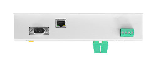
Detachable Connectors
All input, power and relay connectors are detachable for ease of installation. Screw-down connectors are used throughout.
BN Power
Typical battery power can be used to power the device. Its operating range is 9 to 36Vdc. The internal power supply is fully isolated.
Serial Terminal Port
Baud rates from 300 to 115,200 are supported. The default Baud rate is 38,400. The Terminal Port can be used with a USB-to-serial adapter.
Ethernet Port (opt.)
The Ethernet Port option allows remote users to access the device via a LAN connection. Additionally, if a time server is accessible it can be used to maintain 100% RTC accuracy.
CRD‑14A Documentation

On the Inside
Up to 128 days of Event Storage
Irrespective of how many days are saved in memory, after the memory is filled new data automatically overwrites the oldest data. Similarly, the 129th day overwrites the first day.
297,045 Event Record Storage Capacity (exp.)
Memory can be optionally expanded to 1,264,533 Event Records.
Events Time Stamped to .001 sec.
Time stamping at 1/1000th of a second can be useful when monitoring high speed or short duration electronically generated signals.
Non-Volatile Memory With No Internal Batteries
Event Records and the Setup Database are retained indefinitely, even when power is not applied. There are no batteries or other consumables to replace.
Clock Accuracy ±8 sec. per Month (std.)
Even in the absence of clock synchronization the RTC is highly accurate. The clock will continue to run with a loss of power of up to 30 days duration.
100% Accurate Clock (opt.)
The Ethernet Port option can be used to maintain 100% accuracy of the RTC. Using the Ethernet Port option for this purpose requires an accessible time server.
20 Programmable Alarm Inputs
Each Alarm Input can be programmed to report the logical condition and time duration of any potential fault or failure condition.
Records Numerous Crossing Fault Conditions
Alarm Inputs can be programmed to indicate short and long duration power outages, gate up and down problems, crossing duration, etc.
Alarm Input Events Logged as Records
Event Records are saved in memory as Alarm conditions transition to and from active and cleared states. A Query limited to Alarm Inputs can be performed at any time.
10 User-Controlled Counters
Each Digital Input includes a Counter. Counter values range from 0 to 65,535. They can be individually disabled or enabled to increment on either an On or Off transition of the Digital Input.
8 Programmable Virtual Inputs
Logical conditions among any 4 Digital, Analog or other Virtual Inputs are automatically detected using the Virtual Input feature. These conditions, that may be of special interest to the user, are logged to memory as Event Records.
8 Programmable Timer Inputs
The duration between any 2 events can be measured and reported as an Event Record. User-defined High and Low Limit Values can be used to detect abnormally long or short durations.
Flash Rate Reporting and Measurement
This feature can be used to precisely measure the flash rate. Additionally, the flash rate is reported in each Event Record when flashing is present.
Internal Temperature Sensor
The internal temperature of the device is continuously monitored. Excessively hot or cold conditions are logged to memory as Event Records.
Can be Upgraded to CAR‑14A
Should the crossing eventually warrant automatic Alarm Reporting, the CRD‑14A can be upgraded to a CAR‑14A.