On the Outside
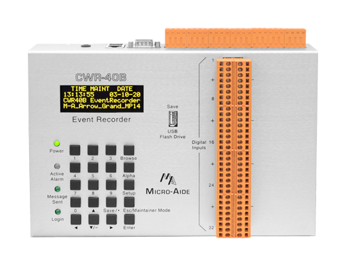
80-Character OLED Panel
The OLED display panel provides excellent contrast for improved visibility. It also provides improved temperature stability.
20-Position Keypad
The OLED display panel and Keypad allow an onsite user to fully access the device without using a PC. Access is protected by an 8-digit Passcode.
4 Front Panel LEDs
LEDs are used to indicate Power, Active Alarm, Alarm Message transmission and user login status.
USB Host Port
A user-selected range of Event Records can be quickly saved to a USB Flash Drive. Reports can be digitally signed to provide 100% data integrity. The port can also be used to perform software updates, and saving and restoring of the Setup Database.
32 Digital Inputs
All Digital Inputs are fully isolated by optical means. On/off conditions are 9 to 36Vdc and 0 to 1Vdc, respectively.
Detachable Connectors
All input, power and relay connectors are detachable for ease of installation. Tension clamp connectors are used throughout.
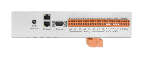
GPS Receiver (opt.)
Without user intervention, the internal real-time clock (RTC) can be kept 100% accurate by using the GPS Receiver option. The option comes with an external, ruggedized antenna.
Dual Ethernet Ports
Both ports operate concurrently and independently. They can be accessed locally or remotely via cell modem or direct connection to a LAN/WAN.
8 Analog Inputs
Positive and negative DC and AC voltages are continuously monitored by the Analog Inputs. Separate user-defined High and Low Limit Values are used to identify abnormal conditions.
2 Relay Outputs
User-programmed Virtual Inputs control the operation of dual Relay Outputs. Each can be used to provide an external indicaton of a fault or failure condition.
BN Power
Typical battery power can be used to power the device. Its operating range is 9 to 36Vdc. The internal power supply is fully isolated.
Small Mounting Footprint
The Event Recorder's small mounting footprint and weight makes it useful in portable study applications.
CWR‑40B Documentation

On the Inside
Ethernet Ports Send Alarm Messages
Either Ethernet Port can be used to provide Alarm messaging to the customer's back-of-house server. The HTTP-Get method is employed for the transmission of Alarm messages.
20 Programmable Alarm Conditions
Alarms can be programmed to report the logical condition and time duration of any potential fault or failure condition.
Reports Numerous Crossing Fault Conditions
Alarms can be programmed to indicate short and long duration power outages, gate up and down problems, active crossing duration, etc.
Provides Periodic Health Check Messages
At pre-set intervals the device will transmit messages that confirm the viability of the device and supporting network.
Supports LAN/WAN-Based Applications
In cases where a LAN, WAN or VPN is available, a direct connection to the network provides remote access. A cell modem is not required.
Non-Volatile Memory With No Internal Batteries
Event Records and the Setup Database are retained indefinitely, even when power is not applied. There are no batteries or other consumables to replace.
100% Accurate Clock (via SNTP)
Both Ethernet Ports implement the SNTP-Unicast protocol. This allows the device's RTC to be kept 100% accurate by periodic communications with a network accessible time server.
Maintainer Mode Disables Alarm Reporting
While Maintainer Mode is enabled the sending of Alarm messages can be temporarily suspended. This can be useful when the crossing is being tested or repaired. As a precaution, Maintainer Mode is automatically disabled after a user-defined interval. After the time-out, Alarm message transmission is resumed.
32 Programmable Virtual Inputs
Logical conditions among any 4 Digital, Analog, Alarm or other Virtual Inputs are automatically detected using the Virtual Input feature. They can be very useful in precisely defining an Alarm condition.
32 Programmable Timer Inputs
The duration between any 2 events can be measured and reported as an Event Record. User-defined High and Low Limit Values can be used to detect abnormally long or short durations.
Internal Temperature Sensor
The internal temperature of the device is continuously monitored. Excessively hot or cold conditions are logged to memory as Event Records.
Up to 128 days of Event Storage
Irrespective of how many days are saved in memory, after the memory is filled new data automatically overwrites the oldest data. Similarly, the 129th day overwrites the first day.
261,632 Event Record Storage Capacity (exp.)
Memory can be optionally expanded to 3,055,104 Event Records.
Events Time Stamped to .01 sec.
Time stamping at 1/100th of a second can be useful when monitoring high speed or short duration electronically generated signals.
Tamperproof Event Records
At the user's discretion, an Event Record report can be digitally signed. The signature can be used to detect alterations of the report.
Flash Rate Reporting and Measurement
This feature can be used to precisely measure the flash rate. Additionally, the flash rate is reported in each Event Record when flashing is present.