On the Outside
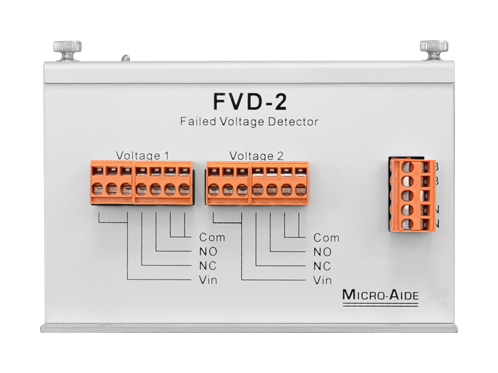
Dual Passive Inputs
Each Voltage Input has a minimum input impedance of 12MOhm. This provides for high levels of isolation and negligible loading effects. DC and AC voltages can be monitored.
Dual Isolated Outputs
Each input circuit has an individual Relay Output. High or low voltage failures will immediately operate the appropriate Relay Output. The relay contacts are dry and fully isolated. Normally open and closed contacts are available.
BN Power
Typical battery power can be used to power the device. Its operating range is 8 to 36Vdc. BN power terminals are fully isolated from the chassis and outputs.
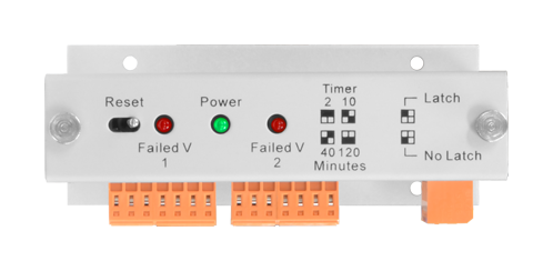
Reset Switch
Voltage failure indications are cleared by pressing the Reset Switch. Latched Relay Outputs are cleared simultaneously.
Dual Status LEDs
If a voltage failure is detected, an individual LED is illuminated. The LED remains illuminated until it is reset.
Power LED
The LED flashes once per second to indicate the device is functionally operative.
Detachable Connectors
All connectors are detachable for ease of installation. Tension clamp connectors are used throughout.
Small Mounting Footprint
The device can be mounted on a shelf or backboard. It can be mounted in any convenient orientation.
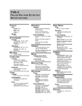
FVD‑2 Documentation
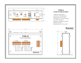
On the Inside
Removable Cover Provides Inside Access
Removing the cover allows access to the Limit Value adjustments, Latch Control Switch and Test Points.
RMS Measurement Improves Accuracy
Like a DVM the device incorporates an RMS measurement. This improves the device's accuracy by filtering out AC and other ripple content.
User Adjustable High Limit Values
Individual High Limit Values are adjusted by rotating a 20-turn potentiometer. The adjustment range is .5 to 48Vdc or .5 to 36Vac.
User Adjustable Low Limit Values
Individual Low Limit Values are adjusted by rotating a 20-turn potentiometer. The adjustment range is .5 to 48Vdc or .5 to 36Vac.
User Selected Failure Durations
The failure duration can be set to 2, 10, 40 or 120 minutes. A short duration failure not meeting the selected criterion is ignored.
Dual High and Low Test Points
A Digital Voltmeter is connected to the Test Points. High and Low Limit Values are set by adjusting the DVM measurement. The ratio of effective Limit Value to measured Vdc is 10 to 1.
2-Position Latch Control Switch
If latching is enabled, the Relay Outputs will remain active until they are reset.
Fully Compatible with any Event Recorder
The dry contacts of the Relay Outputs can be connected to any MICRO‑AIDE CWR or CAR product or non-MICRO‑AIDE product.