On the Outside
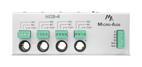
4 Isolated Outputs
Each current sensing circuit has an individual Relay Output. The relay contacts are dry and fully isolated. Normally open and closed contacts are available.
4 Passive Inputs
Each current carrying conductor passes through a separate hole in the device. Currents are passively measured by monitoring each magnetic field. An AC/DC sensitive Hall Effect device is used for this purpose.
BN Power
Typical battery power can be used to power the device. Its operating range is 8 to 40Vdc. BN power terminals are fully isolated from the chassis and outputs.
Test Input
The Test Input terminals can be used to perform a pre-installation bench test. The test current is scaled up 5 fold (e.g., a 2Amp test current appears as 10Amp).
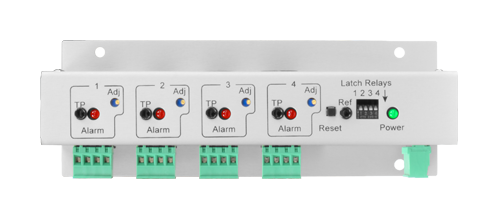
4 Test Points
A Digital Voltmeter is connected to the Test Points. The excessive current Limit Value is set by adjusting the DVM measurement. The ratio of Aac/Adc to measured Vdc is 10 to 1.
4 Status LEDs
If excessive current is measured, an individual LED is illuminated. The LED remains illuminated until it is reset.
4 Limit Adjustments
The individual Limit Values are adjusted by rotating a 20-turn potentiometer.
Reset Pushbutton
Excessive current indications are cleared by pressing the Reset Pushbutton Switch. Latched Relay Outputs are cleared simultaneously.
Latch Control Switches
Excessive current will immediately operate a Relay Output. If latching is enabled, the Relay Output will remain active until it is reset. Each Relay Output can be individually latch enabled or disabled.
Power LED
This LED flashes once per second to indicate the device is functionally operative.
Detachable Connectors
All relay and power/test connectors are detachable for ease of installation. Screw-down connectors are used throughout.
Small Mounting Footprint
The device can be mounted on a shelf or backboard. It can be mounted in any convenient orientation.
HCS‑4 Documentation
On the Inside
Broad Dynamic Current Range
DC and AC currents in the range of 1 to 20Amp can be monitored.
Limit Values Match Current Range
Each of the 4 separate Limit Values can be set from 1 to 20Amp.
Transient Filtering for Track Switch Machines
Typical current draws from a track switch machine are characterized by large transient spikes. The device is designed with a specialized filter to smooth out these transients. The filter, in conjunction with properly set Limit Values, prevents erroneous excessive current indications.
Digital Design Improves Performance
The nearly all digital design of the device makes it stable and accurate over its operating temperature range. It does not require periodic adjustment as it is not prone to drift.
Fully Compatible with any Event Recorder
The dry contacts of the Relay Outputs can be connected to any MICRO‑AIDE CWR or CAR product or non-MICRO‑AIDE product.
Designed to Operate in Harsh Rail Applications
Unlike most commercially available current sensing modules, the device is designed to operate reliably in a typical rail signal facility. Like most MICRO‑AIDE rail products it will operate in ambient temperatures of -40C to +72C.