On the Outside
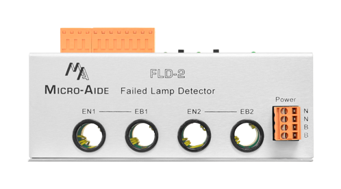
Dual Passive Inputs
Each current carrying conductor passes through a separate hole in the device. Currents are passively measured by monitoring each magnetic field. An AC/DC sensitive Hall Effect device is used for this purpose.
BN Power
Typical battery power can be used to power the device. Its operating range is 10 to 36Vdc. BN power terminals are fully isolated from the chassis.
Dual XR Inputs
The XR inputs are required to determine when the crossing is active and when to monitor for lamp current.
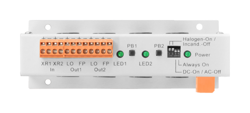
Dual Outputs
Each monitored circuit is equipped with two outputs. The Light Out (LO) indicates one or more lamp failures. The Flash Pulse (FP) pulses high and low as it tracks the detected flashing.
Dual Status LEDs
Separate LEDs indicate the status of each monitored circuit. They are also used as a part of the calibration procedure.
Dual PB Switches
Each monitored circuit uses a separate pushbutton switch. The switches are used as a part of the calibration procedure.
4 Control Switches
Piano-style switches select halogen or incandescent lamp type. DC or AC lamp current can be selected.
Power LED
This LED illuminates when power is applied to the device.
Detachable Connectors
All power, input and output connectors are detachable for ease of installation. Tension clamp connectors are used throughout.
Small Mounting Footprint
The device can be mounted on a shelf or backboard. It can be mounted in any convenient orientation.
FLD‑2 Documentation

On the Inside
Use with any MICRO‑AIDE CWR or CAR Product
The Light Out and Flash Pulse outputs can be connected directly to spare Digital Inputs. Doing so allows the flash rate of each crossing activation to be reported as part of an Event Record.
Detects Single Lamp Failures
A single halogen or incandescent lamp failure is detected within a lamp circuit containing as many as 12 lamps.
Broad Dynamic Current Range
DC currents in the range of 7.5 to 30A can be monitored (5 to 21A for AC).
RMS Measurement Improves Accuracy
Like a DVM the device incorporates an RMS measurement. This improves the device's accuracy by filtering the effects of transient currents.
EB and EN Conductors are Monitored
Current is monitored separately for each EB and EN conductor. This allows the device to discern flashing and to provide the FP output. An XOR input is not required by the device.
Automatic Source Voltage Compensation
The device is powered by the source of power to the monitored circuits. Variations of the source voltage are detected and used to adjust the calibrated lamp failure current levels.
Digital Design Improves Performance
The nearly all digital design of the device makes it stable and accurate over its operating temperature range.
User-Initiated Calibration Procedure
The device uses a simple calibration procedure that allows its performance to be optimized for each crossing installation.
Designed to Operate in Harsh Rail Applications
Unlike most commercially available current sensing modules, the FLD‑2 is designed to operate reliably in a typical rail signal facility. Like all MICRO‑AIDE rail products it will operate in ambient temperatures of -40C to +72C.