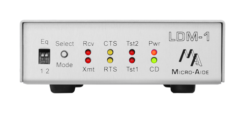
On the Outside
Equalization Switches
The two piano-style switches provide four different equalizations settings. Each equalization setting compensates for a different degree of cable-related signal loss.
Select Mode Switch
This pushbutton switch selects normal operational mode or one of three test modes.
Data LEDs
Separate LEDs indicate the presence of transmit and receive data.
CTS and RTS LEDs
These LEDs are used to indicate the modem's hardware flow control activity.
Test Mode LEDs
A pair of LEDs are used to indicate normal operational mode and to identify one of three test modes.
Power LED
This LED is illuminated when power is applied to the modem.
Carrier Detect LED
This LED illuminates when a far-end LDM is occupying the receive channel.
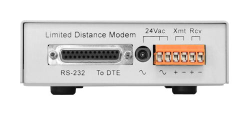
DCE Connector
A DB‑25 female connector is used to connect to the DTE. The connector is configured as a DCE device.
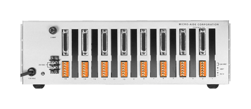
Power In Connector
The LDM‑1 is powered by a 24Vac wall mount transformer which is provided with each modem. The LDM‑1 PI is powered from within the LDM‑16 by a 24Vac transformer.
Detachable Connector
A 6-position detachable connector is used to terminate the ± inputs of the transmit and receive pairs. Screw-down connectors are used throughout.
LDM Documentation
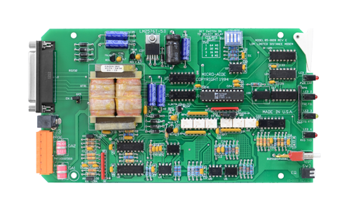
On the Inside
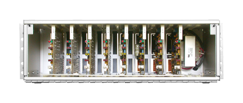
Point-to-Point and Multi-Drop Networks
A pair of modems can be connected to form a point-to-point network. Alternatively, as many as 8 modems can be connected in a multi-drop configuration.
Selectable Termination Settings
150 Ohm terminations are selected at the end points of a multi-drop network. For optimal network performance the the mid-cable modems are not terminated.
Full Duplex Operation Over 4 Wires
Separate transmit and receive cable pairs allow the DTE devices to communicate simultaneously in full duplex mode.
Data Transparent Asynchronous Operation
The operation of the modem is completely asynchronous and transparent to all data. Data encodings with or without parity, multiple start and stop bits are permitted.
Supports a Broad Range of Baud Rates
The asynchronous design of the modem supports standard and non-standard Baud rates ranging from 75 to 19,200.
Three Diagnostic Test Modes
Analog loopback decodes the received analog signal and sends it back via the transmit channel. Digital loopback recieves and then transmits RS‑232 data in and out of the DTE port, respectively. The third test enables a test pattern generator that continuously transmits an ASCII "U" character via the DTE port.
Expanded Operating Temperature Range
The modem will operate over a temperature range from -20C to +70C.
Selectable RTS to CTS Delays
This delay allows the network to be fully idle before another transmission is initiated. Delays of 8, 16, 32 or 64 msec. can be selected.